

 English
 русский
 Español
 عربى
عربى 中文简体
中文简体
 中文简体
中文简体
Content
Function and Critical Role of Pulverizer Discs
A pulverizer disc is a high-wear rotating component within grinding mills that applies compressive and shear forces to reduce bulk solids like coal, limestone, or minerals into fine powder for industrial processing. These discs serve as the primary interface between mechanical energy input and material size reduction, directly determining throughput efficiency, particle size distribution, and operational costs. Disc wear rates typically range from 0.5mm to 3mm per 1,000 operating hours depending on material abrasiveness and disc metallurgy, making them the most frequently replaced consumable in vertical roller mills and disc pulverizers. Selecting the correct disc geometry, alloy composition, and hardfacing pattern is essential for maintaining target fineness (e.g., 70–90% passing 200 mesh for coal) while minimizing unplanned downtime and specific power consumption.
Disc Configurations and Application-Specific Designs
Pulverizer discs are not universal components; their design must match feed material characteristics, mill type, and production targets. Three primary configurations dominate industrial applications:
- Flat Grinding Discs: Used in Raymond-type mills for soft to medium-hard materials (coal, gypsum); feature replaceable liner segments bolted to a cast steel base plate for cost-effective maintenance.
- Tire-Shaped Discs: Employed in Loesche and Pfeiffer vertical roller mills for cement raw meal and slag; curved profile matches roller contour to create optimal nip zone pressure distribution across 1,200–2,000mm diameters.
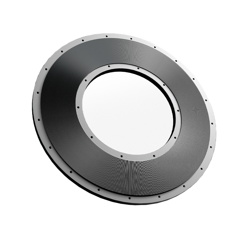
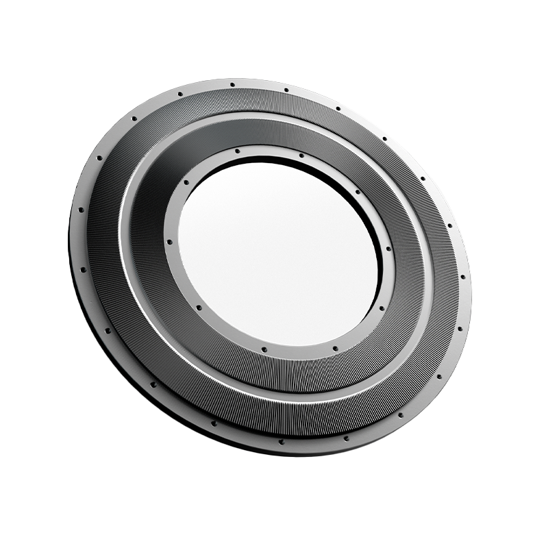
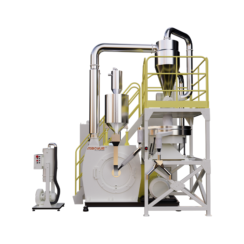
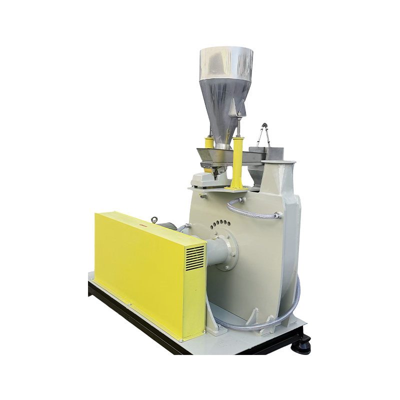
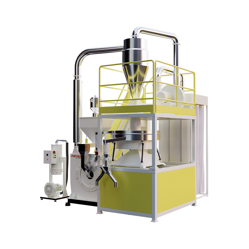
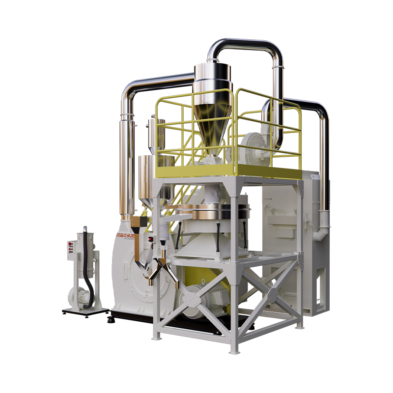
- Serrated/Toothed Discs: Found in impact-disc pulverizers for plastics, chemicals, and food processing; intermeshing teeth generate shear-dominant comminution at 3,000–6,000 RPM for heat-sensitive materials.
Geometry Impact on Performance Metrics
Disc surface topography directly influences grinding efficiency. Grooved or riffled patterns increase material retention time and recirculation ratio, improving fineness control but raising power draw by 8–15%. Smooth profiles reduce specific energy consumption by 5–10% but may produce coarser product distributions. Modern computational fluid dynamics (CFD) modeling enables custom groove geometries optimized for specific feedstocks, yielding throughput improvements of 10–20% over generic designs without increasing motor load.
Material Selection and Wear Protection Strategies
Disc longevity depends entirely on metallurgical choices matched to abrasive conditions. Base materials provide structural integrity while surface treatments resist erosion and impact fatigue.
| Material System | Hardness (HRC/HV) | Best Application | Relative Cost Factor |
|---|---|---|---|
| Ni-Hard Cast Iron | 45–55 HRC | Coal, low-silica minerals | 1.0x (Baseline) |
| High-Chrome White Iron | 58–65 HRC | Cement clinker, iron ore | 2.5–3.0x |
| Tungsten Carbide Overlay | 1,200–1,600 HV | High-silica sand, bauxite | 4.0–6.0x |
| Ceramic-Metal Composite | 1,800–2,200 HV | Extreme abrasion + impact | 8.0–12.0x |
Hardfacing Versus Solid Alloy Economics
For large-diameter discs (>1,500mm), hardfacing worn surfaces with tungsten carbide weld deposits often proves more economical than full replacement. A properly executed overlay restores original dimensions at 30–50% of new disc cost while extending service life by 8,000–15,000 additional hours. However, this approach requires precise thermal management during welding to prevent cracking in the base metal; post-weld stress relief heat treatment is mandatory for discs exceeding 60mm thickness.
Wear Monitoring and Replacement Decision Criteria
Proactive disc management prevents catastrophic failures and maintains consistent product quality. Key indicators triggering inspection or replacement include:
- Vibration Amplitude Increase: Baseline vibration rising >25% suggests uneven wear or segment loosening; immediate shutdown required if acceleration exceeds 7.1 mm/s RMS per ISO 10816-3.
- Power Draw Deviation: Specific energy consumption increasing >10% above baseline indicates reduced grinding efficiency from worn profile geometry.
- Product Fineness Drift: Coarse fraction (+200 mesh) exceeding specification limits despite classifier adjustments signals insufficient compression zone depth.
- Visual Inspection Thresholds: Maximum allowable wear depth varies by design; typical limits are 40–60mm for flat discs and 25–35mm for tire profiles before reconditioning becomes uneconomical.
Implement ultrasonic thickness mapping during scheduled outages to track wear progression quantitatively. Documenting wear rates against tonnage processed enables predictive replacement scheduling, reducing emergency downtime by an average of 60–80 hours annually per mill according to industry benchmark studies.