

 English
 русский
 Español
 عربى
عربى 中文简体
中文简体
 中文简体
中文简体
Content
Selecting the Correct Pulverizer Disc for Target Particle Size
The pulverizer disc is the primary determinant of final particle size distribution, throughput capacity, and energy efficiency in mechanical size reduction equipment. Choosing a disc profile that matches your material's friability and target mesh size is more critical than motor horsepower alone. A mismatched disc can reduce output by up to 40% and increase wear rates threefold, regardless of machine specifications.
For most industrial applications ranging from plastics to minerals, the optimal disc configuration achieves 85-95% yield within ±10% of the target mesh while maintaining specific energy consumption below 0.15 kWh/kg. This balance is achieved through precise alignment of disc geometry, rotational speed, and gap settings rather than brute force grinding.
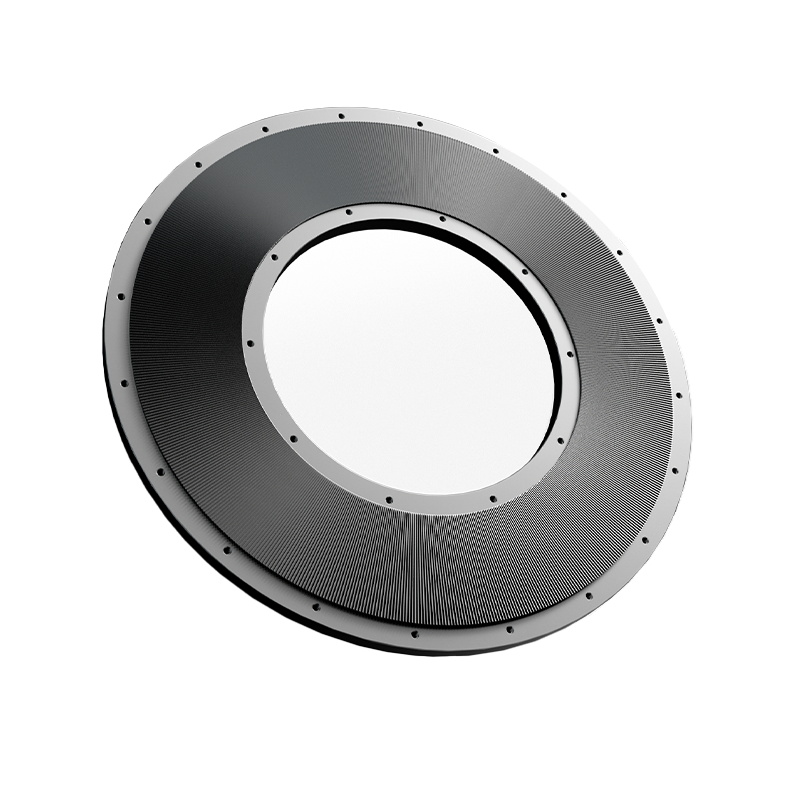
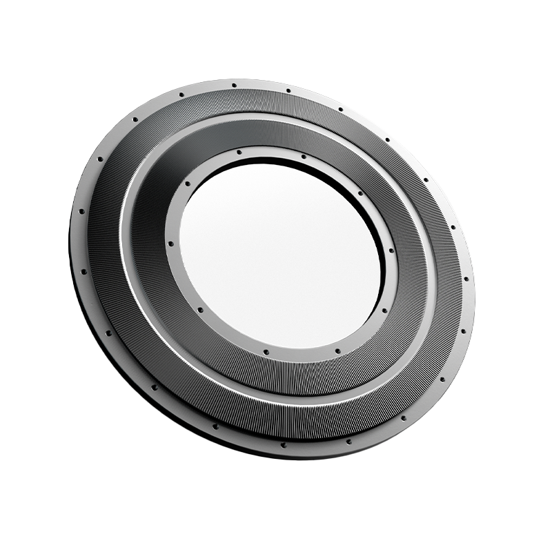
Disc Geometry Profiles and Their Applications
Pulverizer discs are not interchangeable; each profile generates distinct fracture mechanics suited to specific material classes. Understanding these differences prevents costly trial-and-error testing and ensures consistent product quality.
| Disc Type | Best Material Class | Typical Mesh Range | Key Advantage |
|---|---|---|---|
| Toothed / Impact | Brittle minerals, ceramics | 20-80 mesh | High throughput, coarse control |
| Serrated / Shear | Plastics, elastomers, fibers | 40-200 mesh | Clean cut, minimal heat generation |
| Corrugated / Attrition | Food, chemicals, pigments | 100-400 mesh | Fine powder, narrow PSD |
| Smooth / Compression | Waxy or oily substances | Variable | Prevents clogging, flaking action |
Why Serrated Discs Dominate Plastic Recycling
Thermoplastics like PVC and PE deform rather than fracture under impact. Serrated discs use shearing edges at 15-30° rake angles to slice material cleanly, generating 60% less heat than toothed alternatives. This thermal management prevents melting and re-agglomeration, which is the primary cause of screen blinding in plastic pulverization.
Material Selection for Wear Resistance and Contamination Control
Disc metallurgy directly impacts service life, product purity, and operating costs. The optimal material balances hardness against toughness based on feedstock abrasiveness and regulatory requirements.
- D2 Tool Steel: Standard choice for general-purpose grinding; offers good wear resistance at moderate cost. Typical lifespan of 800-1,200 hours on non-abrasive plastics before requiring resurfacing.
- Tungsten Carbide Tipped: Essential for silica-rich minerals, glass-filled polymers, or ceramic powders. Extends service life by 5-8x compared to D2 steel but costs 3-4x more upfront. Justified when downtime frequency exceeds monthly intervals.
- Stainless Steel (316L/420): Mandatory for food, pharmaceutical, and chemical applications where iron contamination is unacceptable. Lower wear resistance than tool steel but meets FDA/USP compliance. Expect 30-50% shorter life versus D2 in equivalent conditions.
- Ceramic-Coated: Emerging option combining steel substrate toughness with alumina/zirconia surface hardness. Reduces metal-to-metal contact and static buildup in fine powder applications. Best for <100 micron targets where electrostatic adhesion causes yield loss.
Gap Adjustment and Operational Optimization
The inter-disc gap is the single most adjustable parameter controlling output fineness and production rate. Proper calibration compensates for wear and adapts to batch-to-batch feedstock variability without hardware changes.
Establishing Baseline Gap Settings
Start with manufacturer-recommended gaps as initial setpoints, then refine empirically. For corrugated discs targeting 200 mesh, begin at 0.010-0.015 inches (0.25-0.38mm). Reduce in 0.002-inch increments while monitoring amperage draw; a >15% current spike indicates over-grinding or disc contact. Document the sweet spot where yield peaks without excessive power consumption.
Compensating for Progressive Wear
As disc edges dull, effective cutting clearance increases even if mechanical gap remains constant. Implement a wear-tracking protocol: measure particle size distribution every 50 operating hours and adjust gap tighter by 0.001-0.003 inches to maintain specification. When adjustment no longer restores target PSD, schedule resurfacing or replacement. Ignoring this drift allows oversized particles to pass, contaminating downstream processes and triggering customer rejections.
Maintenance Protocols to Maximize Disc Service Life
Proactive maintenance extends disc longevity far beyond reactive replacement cycles. Most premature failures stem from preventable operational abuses rather than normal wear.
- Daily Visual Inspection: Check for chipped teeth, cracked segments, or embedded foreign objects before startup. A single metal contaminant can destroy an entire disc set in minutes.
- Bearing Temperature Monitoring: Worn bearings cause axial runout that creates uneven disc wear patterns. Replace bearings when temperature exceeds 70°C above ambient or vibration surpasses 4.5 mm/s RMS.
- Cooling System Verification: Ensure air or water cooling circuits are unobstructed. Overheating softens disc edges and accelerates wear exponentially; a 20°C rise above design temp can halve remaining life.
- Feed Rate Consistency: Starve-feeding causes disc-on-disc contact; overfeeding induces stall conditions. Maintain steady load at 80-90% of rated amperage for optimal wear characteristics.
- Scheduled Resurfacing: Don't wait for complete failure. Light grinding at 60-70% wear depth restores geometry at 20% of replacement cost and prevents catastrophic damage to mating components.